Through this activity you will find out how much you weigh on the Moon and on the other Planets of the Solar System.
During this activity we will use the Arduino UNO board. It is a hardware platform used to build robotics, electronics and automation projects, on which a software (in C language) is loaded that will allow you to control a series of sensors, connected to the board, and interact with them.
In addition to the Arduino UNO board, we will use 9 buttons, one for each Planet of the Solar System and one for the Moon, a square platform, preferably in wood, of about 40 cm which will act as a base for the ladder, 4 load cells with a capacity of 50 kg (in this way we can measure a maximum of 200 kg) and finally we will need the HX711 module. This component is very important for amplifying the electrical signal from the load cells. 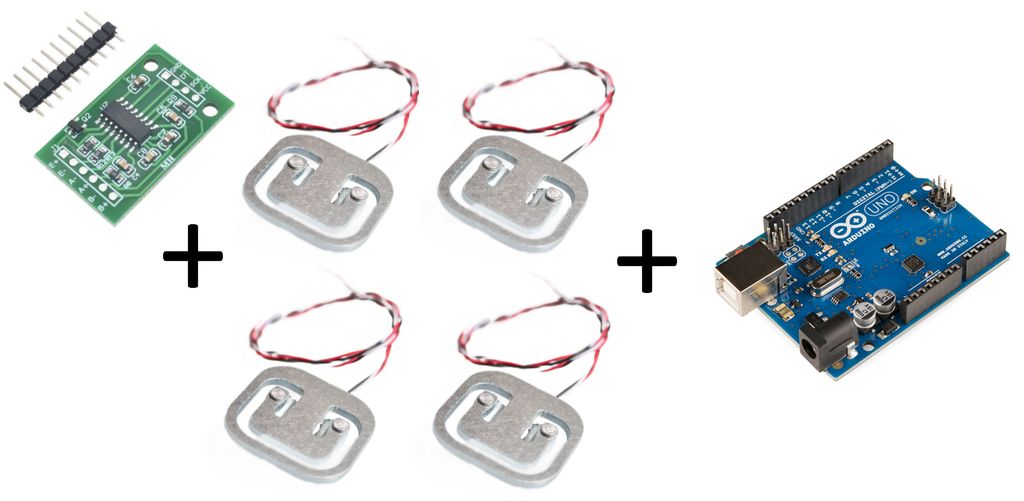 In the first step, we will realize the base of the scale. First of all we take the platform and with some glue attack the load cells on the four corners of the platform. To do this we can use a little hot glue which – I recommend – should only be applied on the external edge of the sensor. This is because the load cell takes advantage of the variation in electrical resistance that some materials have when subjected to compression or traction. The heart of the sensor, are the strain gauges which, suitably positioned on the load cell, provide sufficient indications to size the stress. The resistance electric strain gauge consists of a grid of very thin metal wire rigidly applied on a plastic support. The strain gauge is used by gluing it on the surface of the body whose deformations are to be measured. The wire follows the deformations of the surface to which it is glued, lengthening and shortening together with it; these dimensional variations cause a variation in the electrical resistance of the wire. By measuring these variations, it is possible to trace the extent of the deformation that caused them. Resistance variations are interpreted by the HX711 module which allows Arduino to obtain precise indications on the weight to which the cells are subjected. In order for the module to correctly detect the change in weight and communicate them to the Arduino board, it is necessary to connect the various load cells appropriately following the diagram below.
 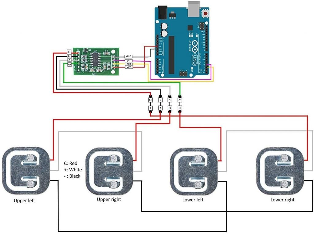 Connections between load cells and HX711 module:
Upper left load cell:
Red wire —> E- pin on HX711 module;
White wire —> White wire upper right load cell;
Black wire —> Black wire lower left load cell.
Upper right load cell:
Red wire —> A- pin on HX711 module;
White wire —> White wire upper left load cell;
Black wire —> Black wire lower right load cell.
Lower left load cell:
Red wire —> A+ pin on HX711 module;
White wire —> White wire lower left load cell;
Black wire —> Black wire upper right load cell.
Lower right load cell:
Red wire —> E+ pin on HX711 module;
White wire —> White wire lower left load cell;
Black wire —> Black wire upper right load cell.
Connections between HX711 module and Arduino:
GND HX711 module —> GND Arduino;
VCC HX711 module —> 5v Arduino;
CLK HX711 module —> pin 2 Arduino;
DOUT HX711 module —> pin 3 Arduino.
As can be seen from the diagram before, some wires of the load cells are connected together to form what is called the Wheatstone bridge. This arrangement allows the loads to be combined and measured simultaneously on all the different load cell sensors.
After making these connections, we are now ready to connect the 9 buttons to the Arduino board. They will be connected and programmed in such a way that – once pressed – they will provide the weight that I could have had on a certain planet on the Arduino serial monitor. The Arduino buttons will be connected with one pin to the ground instead the other pin will be connected to one of the digital outputs of the Arduino board. The connection diagram is shown below. 
Connections between buttons and Arduino board:
Mercury button —> pin 4;
Venus buttun —> pin 5;
Earth button —> pin 6;
Moon button —> pin 7;
Mars button —> pin 8;
Jupiter button —> pin 9;
Saturn button —> pin 10;
Uranus butto —> pin 11;
Neptune button —> pin 12.
In this activity we decided to connect the buttons in this way. However the order can be changed as long as the underlying code is also changed.
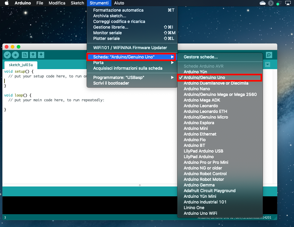
After making these connections, we can move on to programming the Arduino board. First we connect, with its cable, the Arduino board to our PC where we previously installed the software to control and program the Arduino board. After opening the Arduino IDE, we go to tools/board and select Arduino/Genuino Uno. Then we go to tools/door and select the port to which our Arduino is connected. In this way we have set the Arduino working environment and we can start writing the code for our scale.
 |
 |
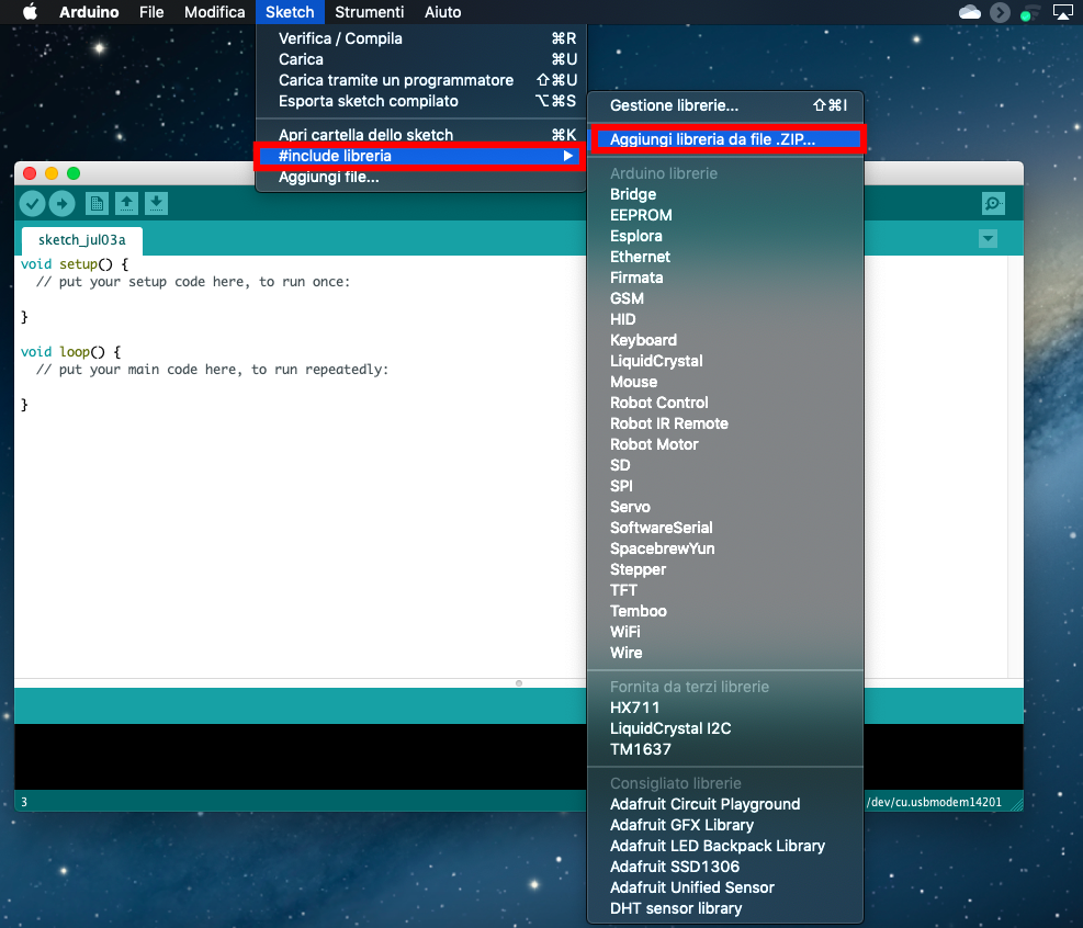
At this point we have to load the library that will allow Arduino to correctly interpret the data obtained by the HX711 module. The library can be downloaded here. To import the library into the Arduino environment just click on Sketch/#include library/add library from zip file, from here just search for the zip file you just downloaded and click on it. In this way Arduino will insert the library in question into the program.
After these operations, we are ready to calibrate the balance. This operation is very important because the load cells provide, due to their construction characteristics, results that are also significantly different from each other. Therefore to have a correct weight measurement it is necessary to introduce a scale factor within the program. To determine the scale factor it is essential to use a calibration program and a sample weight of known value. To do this we use the program which can be downloaded from here.
First of all we have to open the calibration sketch in the Arduino IDE (file/open and then select the calibration.ino file) and load it on the board, without placing any weight on the plate of our scale. We open the Arduino serial monitor (to do this just click on the magnifying glass icon located at the top right of the Arduino work environment). After that the first value is read on the screen, we place on the plate, an object of known weight. A series of values will begin scrolling on the serial monitor which represent the weight of the object measured by the load cells. Obviously these values will not represent the real weight but, using the “a” and “z” keys, we can modify the calibration_factor (calibration factor) until the weight that we read is equal to the weight of our sample object. Once we get the true weight of the object, we take note of the calibration_factor, which will then be inserted into the final program of the balance. Warning: the calibration_factor can be both positive and negative.
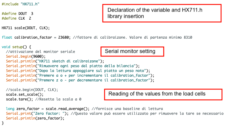
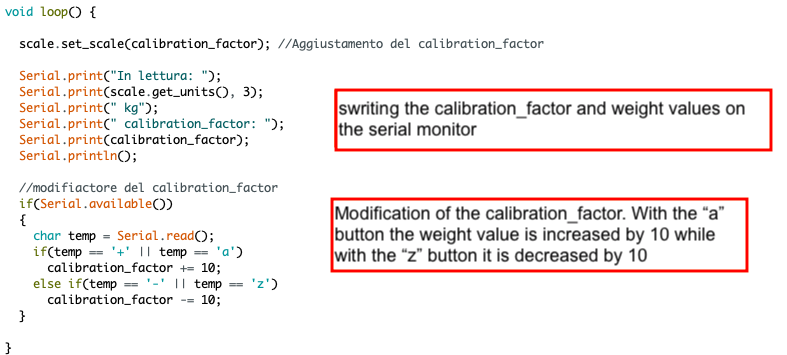
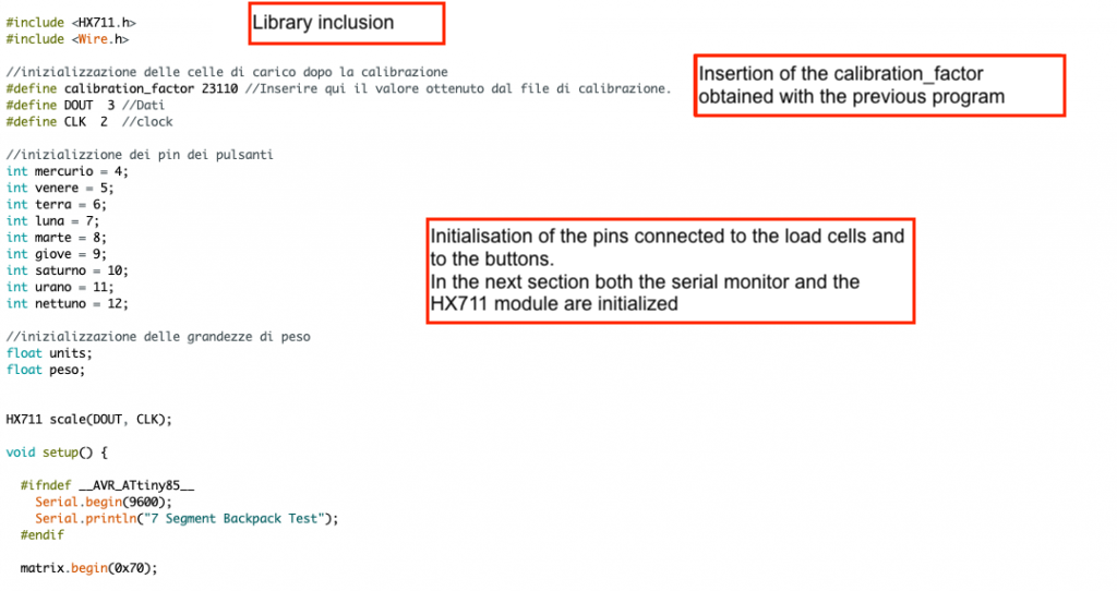
After determining the calibration_factor, we load the scale.ino sketch into the Arduino IDE. This is the sketch that will allow the scale to function properly. Before running the software it is necessary to modify the factor_factor value by inserting what we have determined with the previous program. At this point we load the program on the Arduino board, which can be downloaded from here, and open the serial monitor.
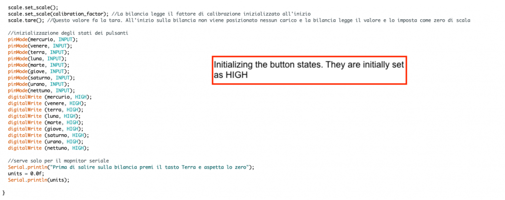
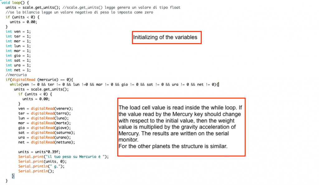
Now all we have to do is get on our scale and, by clicking on the various buttons, we can read on the serial monitor the value of our weight on the various planets of the Solar System!

