Through this activity, you will be able to discover how the variation of a magnetic field may produce an electric current, just as in the dynamo of a bycicle.
To this aim, we shall use Arduino UNO, an hardware platform used in order to build projects of robotics, electronics and automation, on which we can upload a software (in C language), which will enable us to check a series of sensors connected to the card itself, and interact with them.
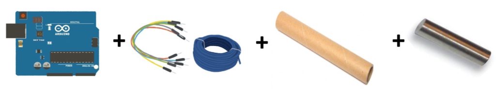
In this project, Arduino will exclusively act as voltmeter o, allowing us to measure the tension induced by the variation of a magnetic field. Over and above the Arduino card, we will need a copper wire, which will be used to create a coil – therefore we are going to need a lot of it; a cardboard tube like that of kitchen paper,around which we will wrap the copper wire; a few connection cables, a magnet, which must slip inside the tube (thus let us not take a large one), and a wooden or cardboard basis.
In this project, we will see how the current flowing inside the circuit will not be produced by a battery or pile, but rather by the movement of a magnet. Indeed, when the magnet falls inside the tube, the magnetic field generated by it will change and produce an induced electric current.
By making various test, you may easily verify that the intensity of the induced current exclusively depends from three quantities:
the variation of the external magnetic field (the higher the magnetic field variation rate, the higher the induced current intensity);
the area of induced circuit(increasing the number of coils of the coil, the greater will be its area);
orientation of the circuit.
Many experiments, conducted since the mid-ninenteenth century, led to the law of electromagnetic induction, also known as law of Faraday – Neumann – Lenz, according to which the value of the induced electromotive force is equal to the relationship between the flow variation of the magnetic field ( the flow of the magnetic field through the circuit is equal to the product of the A area of the circuit multiplied by the module of the magnetic field component, perpendicular to the circuit) and the amount of time necessary to have such variation, whereas the direciton of the induced current – which was created – is always such as to oppose to the variation of the flow itself.
Therefore, we can say that the induced electromotive force exclusively depends from the quick variation of the magnetic field flow through the circuit. This leads us to conclude that, in order to have intensive induced currents, we need to greatly vary the flow of the magnetic field in a short time, for example by quickly changing the magnetic field in the area of the circuit, or by quickly varying the orientation of the circuit with respect to the field lines.
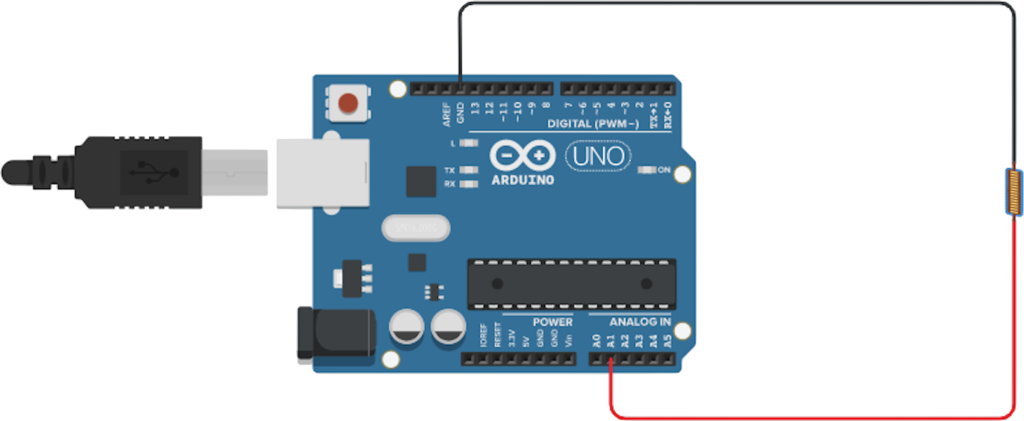
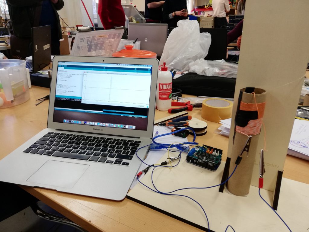
After this short theoretical introduction, let us start with the construction of the circuit. First of all, let us take the tube and start wrapping the copper wire around it, thus creating at least 50 very tight windings (it is essential not to leave empty spaces between one coil and the next). At this stage, it is very important to wrap the wire as tight as possible to the tube, taking care not to deform it and not to tear the wire itself. Moreover, in order to clearly see the effect of variation of the magnetic field, it is useful to leave at least 5 centimetres of tube free on both sides. Once the coil construction is ended, we must connect the extremes to the Arduino board, according to the following diagram.
Connections between the coil and the Arduino card:First head of coil —> pin A1;Second head of coil —> pin GND.
Once we have completed the hardware connection, let us now go over to programming the board.
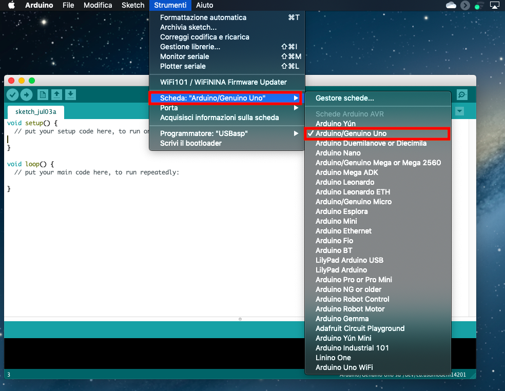
First of all, let us connect, with its cable, the Arduino card to our pc, where we have previously installed the software to control and program the Arduino board. After opening the Arduino IDE, let us go to tools/card and select Arduino/Genuino Uno and then tools/port and select the port to which our Arduino is connected. In this way, we set the Arduino’s working environment, and we can start writing the code for our voltmeter, which you can download here.
First of all, we must open the sketch inside Arduino’s IDE (file/open and then select the file voltmeter.ino) and upload it on the board (in order to do this, just click on the arrow top left side, near the checkmark). After that, let us open Arduino’s serial plotter (tools/serial plotter).
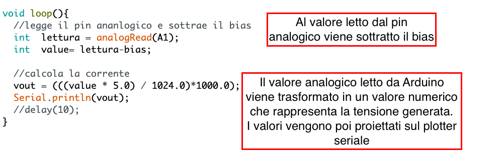
Once completed these preliminary operations, let us prepare to vary the magnetic field, so as to produce induced current. In order to do this, we should place the coil in a vertical position, and make our magnet fall within it. In this way, Arduino will read the value of the induced tension, which flows inside the circuit, showing us its variation in time. We can make the magnet fall more than once, and see what happens. The induced tension might be too small, therefore we can change the multiplicative value of vout, by increasing by a factor of ten (from 1000.0 to 10000.0 for instance) to amplify the signal read by Arduino.
As you can see in the following picture, a wave will appear on the serial plotter, representing the value of tension read by Arduino. As the magnet enters the coil, the flow of the magnetic field, passing inside the coil itself, will change, thus generating a variation of flow other than zero, thus inducing the formation of an electric field, and, as a consequence, of an electric tension.
On the contrary, once the magnet has completely entered inside the coil, the flow of the magnetic field appears to be constant; therefore, its temporary variation is null. In this stage, the induced electric field turns out to be zero, just like the tension passing in the circuit. In the graph, it is represented by a more or less rapid stage, where the tension is zero. Finally, while the magnet goes out from the coil, the flow of magnetic field varies once again over time, with the subsequent formation of an induced electric field and of a tension other than zero.